2.4 Spindle-driven Winders |
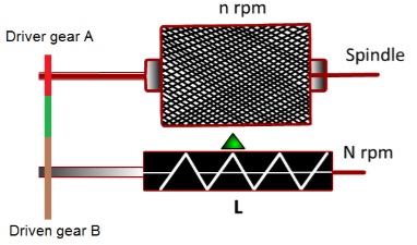
The schematic diagram of a spindle-driven winder is shown in Figure 2.15. The spindle carrying the package is rotating at n r.p.m. A and B (representing the respective tooth number) are the two gears responsible for transmitting the rotational motion from the spindle to traverse mechanism.
|
|
|
Figure 2.15: Drive of spindle-driven winder |
If these gears (A and B) are not changed then the ratio of spindle speed (r.p.m.) and traverse speed (number of traverse/ min) remains same and therefore the value of traverse ratio remains constant. However, the angle of wind changes during the package building which can be understood from the following expressions.
|
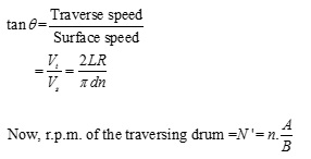
Let R is the number of double traverse made by the traversing device per minure.
|
|
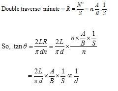
If the traverse is given by a groove drum which requires S revolutions for one double traverse then,
|
| |
As, d increases with the package building, the angle of wind decreases. It is also understood from the above expression that dtanθ remains constant for spindle-driven winders.
|
|
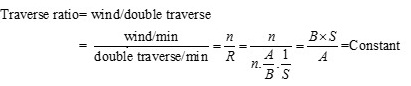
So, for spindle-driven winders, traverse ratio remains constant during the package building.
|
|
|
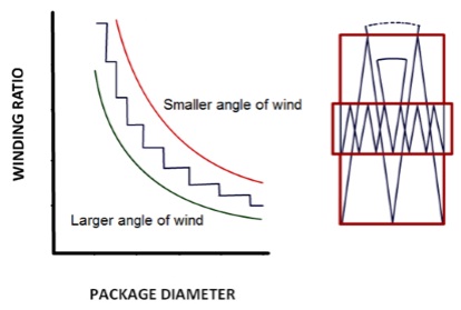
Figure 2.16 depicts the two situations with low and high package diameters. The traverse ration is same in both the cases. However, the angle of wind has reduced from θ to α. |
|
Figure 2.16: Change in angle of wind in precision winder
|
Step Precision Winder or Digicone Winder
|
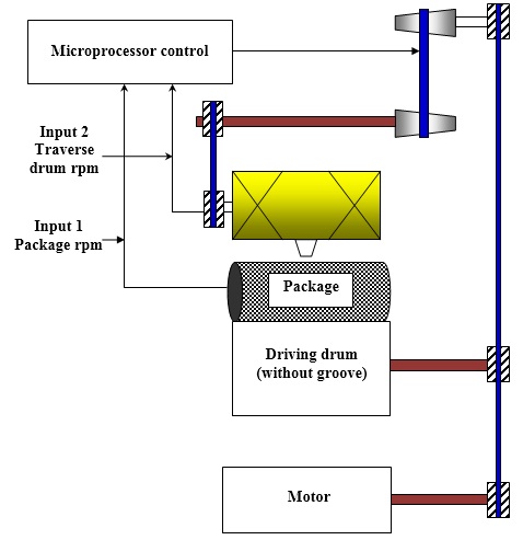
In step precision winder the problem of patterning is prevented by changing the traverse speed proportionately with the package speed (r.p.m.) so that the traverse ratio value remains constant over a period of time. As the package diameter increases, the package r.p.m. decreases as the package is driven by the drum. The traverse speed is also reduced in the same rate. However, after certain time the traverse speed is raised back to the original value in one step thereby moving quickly from one convenient value of traverse ratio to another. The schematic representation of the drive system of step precision winder is shown in Figure 2.17.
|
|
Figure 2.17: Step precision winder |
The driving drum gets motion directly from the motor. However, the motion goes to the traverse guide through a cone drum combinations. As the package r.p.m. reduces, the belt connecting the two cone drums are also shifted towards the left side in a controlled manner. Therefore, the actuating diameter of the driver cone drum reduces whereas it increases for the driven cone drum. So, the speed of the traversing system decreases and traverse ratio remains constant over a period of time. However, the traverse speed cannot be reduced continuously as it will reduce the winding speed and angle of wind continuously. Therefore, after a certain time the connecting belt of the cone drums is shifted towards the right to restore the original value of traverse speed. Therefore, the traverse ratio, governed by the following equation, reduces in steps from one convenient value to the other.
|
|
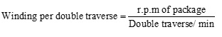
Figure 2.18 depicts the change in traverse ratio with the increase in package diameter.
|
|
Figure 2.18: Change in traverse ratio with package diameter in Digicone winder
|
Angle of wind (θ ) also changes by a small amount (1-2°) when Vt is gradually reduced but again it regain the original value when the Vt is raised back to the original value.
|
Table 2.1 summarizes the differences of three winding principles.
|
Table 2.1: Comparison matrix of winding principles
|
Parameter |
Drum-driven |
Spindle-driven |
Digicone winder |
Angle of wind |
Remains constant |
Decreases with increase in package diameter |
Varies within a very small rang |
Traverse ration |
Decreases with increase in package diameter |
Remains constant |
Remains constants for some time and then decreases in step |
Winding speed |
Remains constant |
Generally increases with package building |
Reduces slowly due to the reduction in traverse speed and then increases to the original value |
Package density |
Increases drastically at the zone of ribbons |
Increases with the increase in package diameter |
Density does not change with package diameter |
|
|
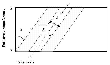
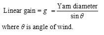
Gain is the distance by which the winding point has to be shifted for avoiding patterning. Linear gain is measured in the direction of perpendicular to the direction of package axis as shown in Figure 2.19. Traverse ratio basically quantifies the number of package revolution within a certain time (one double traverse). Therefore, linear gain cannot be added or subtracted with the traverse ratio. However, linear gain can be divided with the package circumference to obtain revolution gain which can be added or subtracted with traverse ratio.
|
|
Figure 2.19: Gain for cheese package |
If winding takes place in such a manner that the coils wound in two consecutive double traverse is touching each other physically then the gain can be expressed by the following equation.
|
 |